Not all circuit boards are built the same. If you’ve ever ordered a PCB only to realize it wasn’t the right fit for your application, you know how frustrating that mistake can be. Rigid PCBs are the backbone of most electronics, from simple consumer gadgets to complex industrial machinery. But here’s the thing: there isn’t just one type. There are five distinct types, and picking the wrong one can affect performance, cost, and reliability.
This guide breaks down the 5 best types of rigid PCBs you should know before buying. Whether you’re an engineer, a product designer, or a hobbyist, you’ll walk away knowing exactly which type suits your project and why.
What Are Rigid PCBs and Why Do They Matter
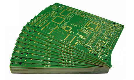
Rigid PCBs are printed circuit boards built on a solid, inflexible substrate that holds its shape permanently. Unlike flexible PCBs that can bend and fold, rigid PCBs maintain a fixed form. That rigidity gives them structural strength, which makes them ideal for applications where the board needs to stay in one place and handle consistent mechanical stress.
The global PCB market was valued at over $75 billion in 2023 and continues to grow steadily, with rigid PCBs making up the largest share of that market. They’re used in computers, smartphones, medical devices, automotive systems, aerospace equipment, and industrial controls.
What makes rigid PCBs the default choice for so many industries? A few reasons stand out:
- They’re more affordable to manufacture at scale
- They offer excellent dimensional stability
- They support complex, multi-layer circuit designs
- They’re easier to repair and test compared to flexible boards
- They handle heat dissipation better in most standard applications
Before you buy, understanding the type you need saves you money, time, and a lot of rework.
5 Best Types of Rigid PCBs
1: Single-Sided Rigid PCBs
Single-sided rigid PCBs are the simplest and most affordable type available. All the components and conductive traces sit on one side of the board, while the other side remains bare. The substrate is typically FR4 fiberglass, which is the industry standard for rigid boards.
Where They’re Used
Single-sided boards work well for straightforward, low-density circuit designs. You’ll find them in:
- Calculators and basic consumer electronics
- LED lighting systems
- Power supplies
- Timing circuits
- Radio and FM transmitter devices
Pros and Cons
| Pros | Cons |
|---|---|
| Lowest manufacturing cost | Limited circuit complexity |
| Easy to design and produce | Not suitable for high-density layouts |
| Fast turnaround time | Single layer restricts routing options |
| Ideal for high-volume orders | Not suitable for advanced applications |
If your project involves a simple circuit with minimal components and you’re working on a tight budget, single-sided rigid PCBs are a solid starting point. They’re widely available and most PCB manufacturers can produce them quickly at low cost.
2: Double-Sided Rigid PCBs
Double-sided rigid PCBs have conductive layers on both sides of the substrate. Holes called vias connect the two sides electrically, which allows for more complex routing and higher component density without increasing the board’s physical size.
Where They’re Used
Double-sided boards are the most commonly used rigid PCBs across mid-range electronics. Applications include:
- Industrial control systems
- Power conversion equipment
- Amplifiers and audio equipment
- HVAC control boards
- Automotive dashboards and sensors
What Makes Them a Popular Choice
The jump from single to double-sided doesn’t just double your routing space. It opens up significantly more design possibilities. Designers can route traces on both sides and use vias to connect them, which reduces the chance of signal interference and allows for cleaner, more organized layouts.
Manufacturing costs are higher than single-sided boards but still reasonable for most projects. For anything beyond a basic circuit, double-sided rigid PCBs hit a good balance between capability and cost.
3: Multilayer Rigid PCBs
Multilayer rigid PCBs stack three or more conductive layers separated by insulating material. Common configurations include 4-layer, 6-layer, 8-layer, and even boards with 12 or more layers for highly complex designs.
Where They’re Used
Multilayer boards handle the most demanding applications in electronics:
- Smartphones and tablets
- Computer motherboards and graphics cards
- Medical imaging equipment
- Aerospace and defense systems
- High-speed data networking equipment
- Server infrastructure
Layer Count and What It Means
Each layer adds routing capacity and design flexibility. A 4-layer board typically has two inner signal layers sandwiched between power and ground planes. This configuration significantly reduces electromagnetic interference (EMI) and improves signal integrity.
Higher layer counts cost more. A 4-layer board might cost 2 to 3 times more than a double-sided board, while a 12-layer board can cost significantly more depending on materials and tolerances. But for complex, high-performance electronics, that investment is necessary.
Multilayer rigid PCBs also require more precise manufacturing processes. Alignment between layers must be exact, and any defect in the lamination process can render the entire board useless. Working with an experienced manufacturer matters here more than with any other type.
4: Flex-Rigid PCBs
Flex-rigid PCBs combine flexible circuit sections with rigid board sections in a single integrated design. The rigid sections hold the components, while the flexible sections connect them. This eliminates the need for external connectors and cables between rigid boards.
Where They’re Used
Flex-rigid PCBs solve problems that neither rigid nor flex PCBs alone can handle:
- Wearable technology and smartwatches
- Foldable smartphones and laptops
- Military and aerospace equipment
- Medical implants and endoscopes
- Camera modules in mobile devices
- Compact automotive electronics
Why They’re Worth the Premium
Flex-rigid PCBs cost more than standard rigid boards, often significantly so. But they offer advantages that justify that cost in the right application:
- They reduce the total number of connectors and solder joints
- They save space in tight enclosures
- They improve reliability by eliminating connector-related failure points
- They handle vibration and movement better than rigid-only designs
- They reduce overall assembly time and complexity
If you’re designing a product that needs to fit into a small, irregular space or involves moving parts, flex-rigid PCBs deserve serious consideration.
Coupling Devices for Rigid PCBs in Flex-Rigid Designs
One technical detail worth understanding is how coupling devices for rigid PCBs work within flex-rigid assemblies. Coupling devices connect different sections of the board or link the board to external systems. In flex-rigid designs, proper coupling ensures signal integrity across the transition between rigid and flexible zones. Common coupling devices include board-to-board connectors, zero insertion force (ZIF) connectors, and spring-loaded contacts. Choosing the right coupling device affects both the electrical performance and the mechanical durability of the final assembly.
5: High-Frequency Rigid PCBs
High-frequency rigid PCBs are built with specialized substrate materials designed to handle signal frequencies above 1 GHz. Standard FR4 boards start losing performance at these frequencies, so high-frequency boards use materials like PTFE (polytetrafluoroethylene), Rogers laminates, or ceramic-filled composites.
Where They’re Used
These boards are critical in applications where signal speed and precision are non-negotiable:
- 5G telecommunications infrastructure
- Radar and satellite systems
- Microwave communication equipment
- RF (radio frequency) modules
- High-speed data transmission systems
- Advanced driver assistance systems (ADAS) in vehicles
What to Look for When Buying
High-frequency rigid PCBs require careful material selection. Key properties to evaluate include:
- Dielectric constant (Dk): Lower and more stable values maintain signal integrity
- Dissipation factor (Df): Lower values mean less signal loss
- Thermal coefficient of dielectric constant: How stable the Dk value stays across temperature changes
- Surface roughness: Affects signal loss at high frequencies
Rogers 4003C and Rogers 4350B are among the most widely used high-frequency laminates. They offer excellent electrical performance with reasonable manufacturability. Expect to pay a premium. High-frequency rigid PCBs can cost 3 to 10 times more than standard FR4 boards depending on the material and layer count.
Key Materials Used in Rigid PCBs
The substrate material defines a rigid PCB’s performance characteristics. Here’s a quick reference:
| Material | Best For | Key Property |
|---|---|---|
| FR4 Fiberglass | General purpose electronics | Cost-effective, durable |
| Rogers Laminates | High-frequency RF applications | Low signal loss |
| Polyimide | High-temperature environments | Thermal stability |
| Aluminum | LED and power electronics | Heat dissipation |
| PTFE | Microwave and radar systems | Ultra-low dielectric loss |
| Ceramic | Aerospace and military | Extreme stability |
FR4 remains the default for most rigid PCBs because it balances cost, performance, and availability well. For specialized applications, the right material choice makes a significant difference in long-term performance.
Coupling Devices for Rigid PCBs
Coupling devices play a critical role in how rigid PCBs connect to other boards, components, and systems. Getting this right affects both signal quality and mechanical reliability.
Common coupling devices used with rigid PCBs include:
- Board-to-board connectors: Direct connection between two rigid PCBs without cables
- Edge connectors: Allow boards to plug directly into slots, common in expansion cards
- Pin headers and sockets: Standard through-hole coupling for prototyping and modular designs
- ZIF connectors: Zero insertion force connectors used with flex sections in flex-rigid designs
- Press-fit connectors: No soldering required, press directly into plated through-holes
- Backplane connectors: High-density connectors used in server and telecom equipment
Choosing the right coupling device depends on your signal frequency, current requirements, board spacing, and expected number of mating cycles. For high-speed signals, impedance-controlled connectors are essential to avoid signal degradation.
How to Choose the Right Rigid PCB for Your Project
With five types to choose from, the decision comes down to a few practical questions:
1. How complex is your circuit? Simple, low-component designs work well with single-sided boards. As complexity grows, move to double-sided or multilayer.
2. What frequency range does your design operate at? Below 1 GHz, standard FR4 works fine. Above 1 GHz, consider high-frequency materials.
3. Does your product need to move or fold? If yes, flex-rigid PCBs are worth the extra cost to eliminate mechanical connectors.
4. What’s your production volume? Higher volumes bring down per-unit costs significantly, especially for multilayer and high-frequency boards.
5. What are your thermal requirements? High-power applications need boards with good thermal management, such as aluminum-backed rigid PCBs or boards with embedded thermal vias.
6. What’s your budget? Single-sided costs the least. High-frequency and flex-rigid cost the most. Multilayer falls in between depending on layer count.
Rigid PCBs vs Flex PCBs

| Feature | Rigid PCBs | Flex PCBs |
|---|---|---|
| Shape | Fixed, inflexible | Bendable, foldable |
| Cost | Lower | Higher |
| Durability | High in static applications | Better in dynamic environments |
| Component density | High (multilayer options) | Moderate |
| Repairability | Easier | More difficult |
| Best use case | Computers, industrial, consumer | Wearables, medical, aerospace |
Flex-rigid PCBs combine both worlds, which is why they’re growing in popularity for compact, high-reliability products.
FAQs
What are rigid PCBs made of?
Most rigid PCBs use FR4 fiberglass as the base substrate. FR4 is a woven glass fabric laminate bonded with epoxy resin. Specialized applications use materials like polyimide, Rogers laminates, aluminum, or PTFE depending on thermal, electrical, and frequency requirements.
What is the difference between rigid PCBs and flex-rigid PCBs?
Rigid PCBs maintain a fixed shape and cannot bend. Flex-rigid PCBs combine rigid sections for component mounting with flexible sections that can bend or fold. Flex-rigid designs eliminate the need for external connectors between rigid boards and are used in compact or dynamic applications.
How many layers can a rigid PCB have?
Rigid PCBs can range from a single layer to over 50 layers in advanced applications. Common configurations are 1, 2, 4, 6, 8, and 12 layers. Most consumer electronics use 4 to 8 layer boards. Complex systems like high-end servers or aerospace equipment may use boards with 16 or more layers.
What are coupling devices for rigid PCBs?
Coupling devices connect rigid PCBs to other boards, cables, or components. They include board-to-board connectors, edge connectors, pin headers, ZIF connectors, press-fit connectors, and backplane connectors. The right coupling device depends on signal speed, current load, mechanical requirements, and the number of expected connection cycles.
When should I choose a multilayer rigid PCB over a double-sided one?
Choose multilayer when your design requires high component density, complex routing that can’t fit on two layers, controlled impedance traces, or reduced electromagnetic interference. Multilayer boards cost more but are essential for smartphones, computers, medical devices, and any application demanding high performance in a compact space.
Are rigid PCBs suitable for high-frequency applications?
Standard FR4 rigid PCBs work up to around 1 GHz. Beyond that, you need high-frequency rigid PCBs made with specialized materials like Rogers laminates or PTFE composites. These materials offer lower dielectric constants and dissipation factors that maintain signal integrity at microwave and millimeter-wave frequencies.
How much do rigid PCBs cost?
Pricing varies widely by type and volume. A simple single-sided board can cost under $1 per unit in high volumes. Double-sided boards typically range from $2 to $10 per unit. Multilayer boards start around $10 and go up significantly with layer count. High-frequency and flex-rigid boards can cost $50 to several hundred dollars per unit depending on complexity.
What industries use rigid PCBs the most?
Consumer electronics, automotive, industrial automation, telecommunications, medical devices, aerospace, and defense are the largest users of rigid PCBs. Nearly every electronic product contains at least one rigid PCB in some form.
How do I know which type of rigid PCB my project needs?
Start with your circuit complexity, operating frequency, mechanical requirements, and budget. Simple low-frequency circuits work with single or double-sided boards. Complex, high-speed, or compact designs need multilayer or high-frequency options. Products with moving parts or tight space constraints benefit from flex-rigid designs.
What is FR4 and why is it the most common rigid PCB material?
FR4 is a flame-retardant fiberglass composite that offers a good balance of mechanical strength, electrical insulation, moisture resistance, and cost. It works well for most general-purpose electronics operating below 1 GHz, which covers the vast majority of products on the market. Its wide availability and established manufacturing processes make it the default choice.
You might like: hire-backend-developers
Wrapping Up
Choosing the right type of rigid PCB before you buy saves time, money, and frustration. Here are the key takeaways from this guide:
- Single-sided rigid PCBs are best for simple, budget-friendly circuits with low component density
- Double-sided rigid PCBs offer more routing flexibility and suit mid-range industrial and consumer applications
- Multilayer rigid PCBs handle complex, high-performance electronics where signal integrity and density matter
- Flex-rigid PCBs combine rigidity with flexibility, making them ideal for compact and dynamic product designs
- High-frequency rigid PCBs are built for RF, microwave, and 5G applications where standard FR4 falls short
Each type has its place. There’s no single best option because the right choice always depends on your specific application, performance requirements, and budget.
Before placing your next order, run through the selection criteria in this guide. Match your project requirements to the right board type and you’ll avoid the costly mistakes that come from choosing the wrong one.
Have questions about which rigid PCB type fits your design? Start with your circuit complexity and frequency range. Those two factors alone will point you in the right direction.